Wind turbines in a wind farm are arranged in the prevailing wind direction. However, we know that wind flow does not necessarily always come from the same direction! For this reason, wind turbines are equipped with a yaw control system that controls the orientation of the turbine toward the wind.
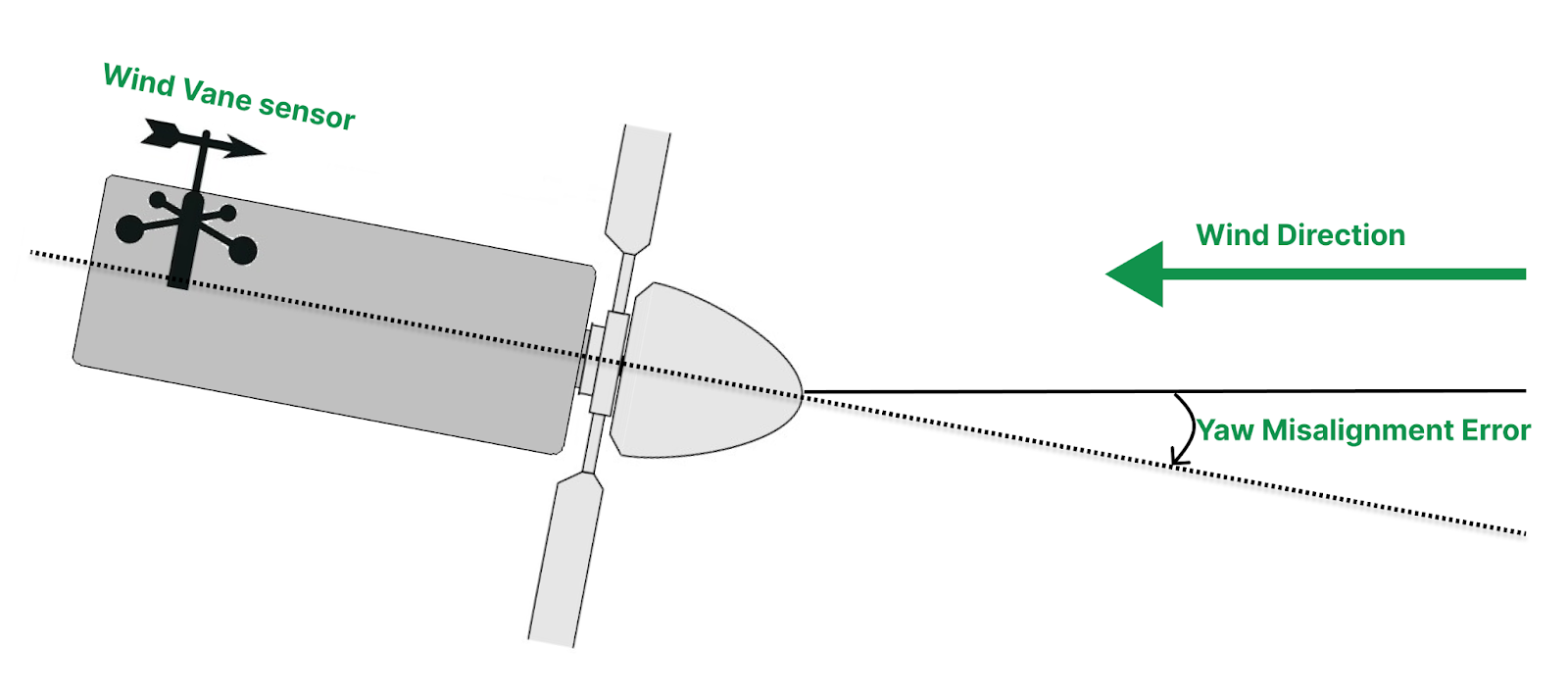
Like most feedback control systems, a wind turbine's yaw control measures the wind direction (through a wind vane sensor). It rotates the wind turbine to minimize the turbine and wind direction error. This type of yaw error is routine and called dynamic yaw misalignment.
But what if the yaw sensor is malfunctioning? Or if we have some software issue causing wrong sensor values? We get incorrect direction information from the wind vane sensor. The turbine tries to align in the wrong direction because it can't see a valid yaw error. It means the turbine is misaligned with the actual wind direction. As a result, the turbine does not get the total energy of the wind and consequently has low output power. Furthermore, getting the wind from the wrong direction may increase the wind turbine's blade load and cause fatigue-related problems. This type of yaw error is hard to track and is called static yaw misalignment.

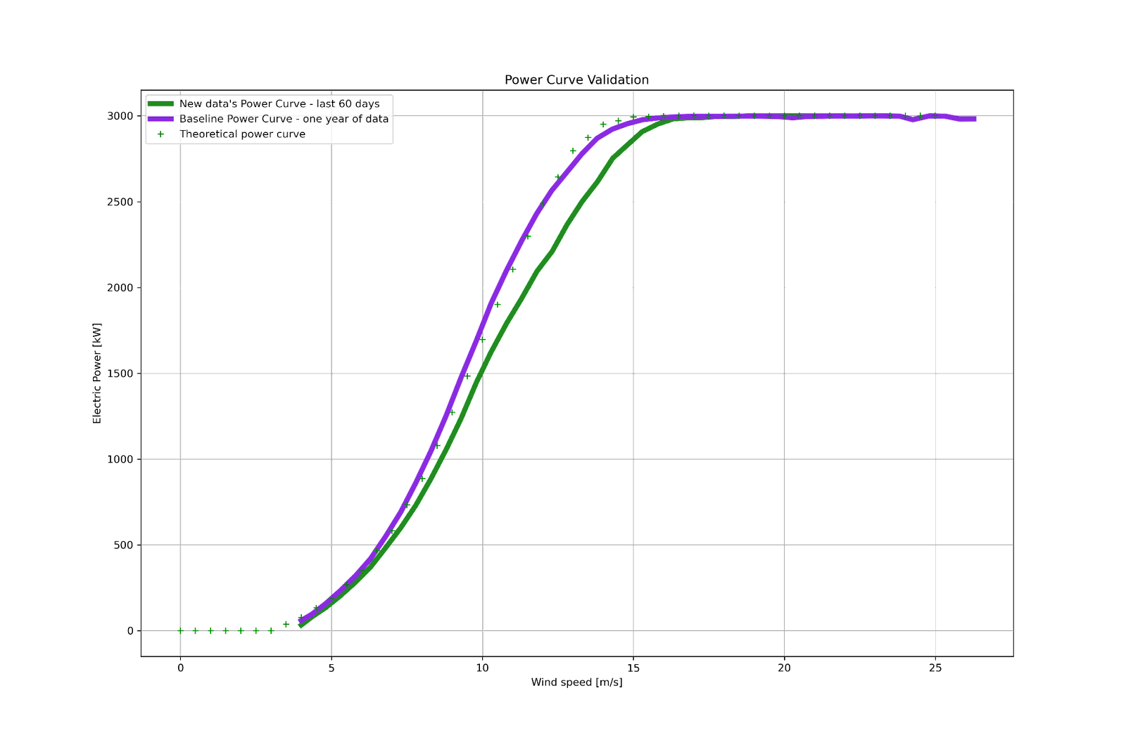
In our previous blog post, Kavaken's Power Booster, we talked about our method of tracking a wind turbine's performance through its power curve. Our tool identifies the yaw misalignment problem efficiently. The type of performance drop in turbine’s power curve due to yaw misalignment is shown in the below figure:

We automatically identify such a performance decline through several statistical tests such as T-tests, MAE, and AEP drop. Compared to the previous year's baseline power curve, the power curve performance has dropped over the last 60 days.
Is this performance drop related to static yaw misalignment?
We need further analysis to verify if the performance reduction is related to static yaw misalignment. First of all, we perform data preprocessing steps in addition to the ones mentioned in the previous blog post, such as availability filters. Section 2 of a power curve is a likely area to investigate the yaw misalignment problem. Section 2 of the power curve starts where wind speed passes the cut-in wind speed value till it reaches the rated wind speed. After this region, the pitch control system has a more powerful effect on power generation. The control mechanism sets the output power on the rated output power in the rated section for even changing wind speeds. Therefore, the yaw misalignment problem, which may lead to lower power generation, is hard to follow in this section. To have a precise analysis, we filter this region's data.
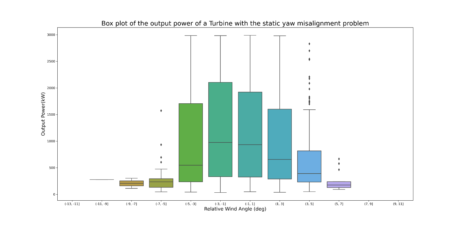
After the data preprocessing steps, we divide the relative wind direction sensor information into several bins based on wind vane sensor resolution. Then we plot and model output power based on these values. We expect the maximum power output to be around 0 degrees if we do not have a static yaw misalignment. However, in the below figure, you see a slight increase in the output power for -2 degrees. This case is the one where that static yaw misalignment occurred.

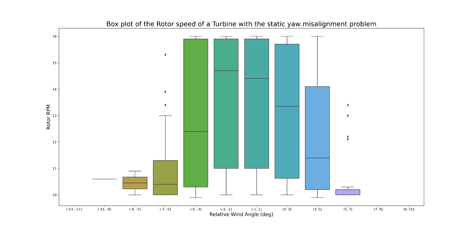
With other SCADA data available, like 10 min rotor speed, you may check this behavior concerning rotor speed vs. relative wind direction. As shown in the first figure wind sensor is located at the top of the wind turbine behind the blades. The wind speed measurements could be uncertain due to airflow distortion. However, we have more reliable data like wind turbine rotor speed. We investigate the static yaw misalignment in rotor speed and relative wind direction figure, similar to output power- relative wind direction. If you spot the same pattern in this plot, you become more confident of static yaw misalignment;

In the above figure, we can observe the error on a similar box plot but in the form of relative wind direction vs. rotor speed. In addition to these plots, we model these relations to automatically identify future abnormal behavior in case of the static yaw misalignment.
After yaw misalignment detection, the next step would be the manual or software calibration of the yaw sensor. Let's solve the static yaw misalignment problem to achieve higher output power, which means higher revenue!


